Questions?
1. when we use 192 xxx ip address, and when we also use 256 xxx ip address ..?
2. Ip address can be separated into two parts, mentioned ?
Answer
1. according to our needs, if we want to create small networks then you should use the ip address classes C, (256 xxx) but if want to create a large network using the ip address class A (192 xxx).
2. netID and hostID
Jumat, 30 Desember 2011
LAN & WAN
1. LAN (Local Area Network)

A local area network (LAN) is a computer network that connects computers in limited areas such as school, home, computer lab, or office buildings. [1] The defining characteristics of LANs, in contrast to the wide area network (WAN), including their usually higher data transfer rates, smaller geographic areas, and lack of need for leased telecommunication networks.
ARCnet, Token Ring and other technology standards have been used in the past, but Ethernet over twisted pair cabling, and Wi-Fi are the two most common technologies currently used to build the LAN.
Early LAN cabling is always based on the various classes of coaxial cable. However, shielded twisted pair is used in the IBM Token Ring implementation, and in 1984 showed the potential of a simple StarLAN unshielded twisted pair Cat3-using the same simple cable used for telephone systems. This led to the development of 10Base-T (and successors) and structured cabling is still the basis of most current commercial LAN. In addition, fiber optic cable is increasingly used in commercial applications.
Because this cable is not always possible, wireless Wi-Fi is now the most common technology in the residence, because the cable required is minimal and is perfect for mobile laptop and smartphone.
Today, most LAN technology based on IEEE 802.3 Ethernet switch using the device, which has a data transfer speed 10, 100, or 1000 Mbit / s. In addition to Ethernet technology, the current 802.11b technology (or so-called Wi-Fi) is also often used to form the LAN. Places that provide LAN connectivity with Wi-Fi technology called hotspots.
On a LAN, each node or computer has its own computing power, in contrast to the concept of terminal dump. Each computer can also access resources on the LAN in accordance with the permissions that have been set. These resources can be data or devices such as printers. On a LAN, a user can also communicate with other users by using the appropriate application.
There are different types of LANs Ethernets are most common for PCs. Most Apple Macintosh networks are based on Apple's AppleTalk network system, which is built into Macintosh computers.
Following characteristics differentiate one LAN from another:
a. Topology: The composition of geometric devices on a network. For example, the device can be arranged in a ring or in a straight line.
b. Protocols: The rules and encoding specifications for sending data. The protocol also determines whether the network using peer-to-peer or client / server architecture.
c. Media: Devices can be connected by twisted-pair cable, coaxial cable, or fiber optic cables. A number of networks without connecting media altogether, communicating instead via radio waves
2. Wan (Wide Area Network)

WAN covers a wide geographical area, such as a province, state or country. WANs often connect multiple smaller networks, such as local area networks (LANs) or metro area network (MAN).
WAN in the world's most popular is the Internet. Some segments of the Internet, such as VPN-based extranet, WAN also within them. Finally, many companies or research WAN networks using leased lines.
WAN network equipment generally use a different and far more expensive than the LAN. Key technologies often found in WANs include SONET, Frame Relay, and ATM
Wide Area Network consists of dark fiber and active communications equipment. Among these are network switches, optical multiplexers and media converters. The WAN will be implemented using 10 Gigabit Ethernet (GbE 10) technology. This is an obvious choice for distances up to ~ 40 km with a pair of transmitter / single receiver, but will also be used for longer distances but cheap and reliable alternatives are available (eg by reuse of existing infrastructure).
Network formed often by seeking the help of telecomm departments that provide leased line facilities. The router is connected to the LAN on one side and a hub mounted at the other end. This is an expensive way to form a WAN (Wide Area Network) networks. WAN (Wide Area Network) networks are often formed using the method of circuit switching. A circuit switching network is established when at the end of one node and at the other end of the terminal is physically connected to each other for further communication. Network nodes is the most common physical switches, hubs and modems. While the terminal is a physical device that perform basic communication, such as telephone, answering machine or printer sometimes. Data moves through the use of network protocols. A protocol is a set of rules that guide the transfer of information. The purpose of the protocol is to detect errors.
WAN devices :
a. WAN Switch
A WAN switch is a multiport internetworking device used in carrier networks. These devices typically switch traffic such as Frame Relay, X.25, and SMDS and operate at the data link layer of the OSI reference model.
b. Access Server
An access server acts as a concentration point for dial-in and dial-out connections.
c. Modem
Modem is a device that interprets digital and analog signals, allowing data to be transmitted over voice-grade telephone lines.
d. CSU / DSU
A CSU / DSU (channel service unit / digital service unit) is a digital-interface device that adapts the physical interface on the device (Data Terminal Equipment) interface from the DCE that the DTE (Data Circuit-Terminating)-enabled devices in the network operator. CSU / DSU also provides signal timing for communication between devices.
e. ISDN Terminal Adapter
An ISDN terminal adapter is a device used to connect ISDN Basic Rate Interface (BRI) connections to other interfaces, such as EIA/TIA-232. A terminal adapter is essentially an ISDN modem.
How to Work a WAN ..??
If we develop a virtual network switching or packet switching network, we often need to relay the frame to transfer the data in (Wide Area Network) WAN. Frame data packets are transferred from one end to the other. There are many types of WAN (Wide Area Network) protocols such as TCP / IP, MPLS, frame relay and ATM. Most (Wide Area Network) WAN using the X.25 protocol, but is well-known WAN is used to transfer packets. X.25 packet switching was established by the exchange, which is a physical node at one end and leased telephone lines at the other end.
NAT
In computer networking, network address translation (NAT) is the process of modifying the IP address of the IP packet header information in transit in traffic routing device.
The simplest types of NAT provides translation 1-1 of IP addresses. RFC 2663 refers to the type of NAT as a basic NAT. It is often also referred to as one-to-one NAT. In this type only NAT IP address, IP header checksum and the checksum of each higher level that includes the IP address needs to be changed. The rest of the package can be left untouched (at least for basic TCP / UDP functionality, some higher-level protocols may require further interpretation). Nat base can be used when there is a requirement for the interconnection of two networks with the IP addresses that are not compatible.
However, it is common to hide the entire IP address space, usually consisting of private IP addresses behind a single IP address (or in some cases a small group of IP addresses) in another address space (usually public). To avoid ambiguity in the handling of the returned package, one-to-many NAT must modify the higher level information such as TCP / UDP port in communication out and should have a translation table so that packets can be correctly translated back again. RFC 2663 uses the term NAPT (network address translation and port) for the type of NAT. Other names include PAT (Port Address Translation), IP masquerading, NAT Overload and many-to-one NAT. Since this is the most common type of NAT is often referred to simply as NAT.
However, most NAT devices today allow the network administrator to configure translation table entry for permanent use. This feature is often referred to as "static NAT" or port forwarding and allows traffic originating in the network "outside" to reach the network host designated in disguise.
NAT and TCP / UDP
"Pure NAT", operating on IP alone, may or may not be totally correct parse protocol relating to IP information, such as ICMP, depending on whether the payload is interpreted by the host on the "inside" or "outside" of translation. Once the protocol stack to go through, even with basic protocols such as TCP and UDP, the protocols will break unless NAT takes action beyond the network layer.
IP packet has a checksum in each packet header, which provides error detection only for the header. IP datagram can be fragmented and the need for NAT to reassemble these fragments to allow correct recalculation of higher level checksums and correct tracking of which packets belong to which connection.
The main transport layer protocols, TCP and UDP, have a checksum that covers all of the data they carry, as well as TCP / UDP, plus a "pseudo-header" that contains the source and destination IP address of the packet carrying the TCP / UDP header. For originating NAT to successfully pass TCP or UDP, must recompute the checksum of TCP / UDP header that is based on the IP address is translated, not the original, and put into the header checksum TCP / UDP packets from the first set of fragmented packets. Receiving NAT must recompute the IP checksum on every packet passed to the destination host, and also recognize and recompute the header TCP / UDP using the retranslated addresses and pseudo-header. This is not really solved the problem. One solution for NAT receiver to reassemble the entire segment and then recompute the checksum is calculated on all packages.
Originating host can do the maximum transmission unit (MTU) discovery of a way to determine the packet size that can be transmitted without fragmentation, and then set does not fragment (DF) bit in the appropriate field of the packet header.
[Edit] Destination network address translation (DNAT)
DNAT is a technique for transparently change the destination IP address of an en-route packet and perform the inverse function for each reply. Each router that is located between two endpoints can perform the transformation of the package.
DNAT is commonly used to publicize the services located on a private network on a publicly accessible IP address. It uses DNAT also called port forwarding, or DMZ when used on the entire server, which becomes exposed to the WAN, to be analogous to the military maintained demilitarized zone (DMZ).
[Edit] SNAT
The meaning of the term SNAT varies by vendor. Many vendors have proprietary definitions for SNAT. An expansion of the public is the source NAT, a partner of destination NAT (DNAT). Microsoft uses the acronym for Secure NAT, in association with ISA Server. For Cisco Systems, SNAT means stateful NAT.
[Edit] Secure network address translation
In computer networking, network address translation process performed in a safe way involves rewriting the source and / or destination addresses of IP packets as they pass through a router or firewall.
An analogy
A NAT device is similar to the phone system in an office that has a public phone number and some extensions. Outbound telephone calls made from the office all seem to come from the same phone number. However, incoming calls that do not specify an extension can not be transferred to individuals in the office. In this scenario, the office is a private LAN, the main phone number is the public IP address, and the extension port number of unique individuals
Routing ( Static & Dinamis)
Routing is the process of directing packets from the source node to destination node on the network that berbeda.Mendapatkan packet to the next hop router they need to perform two basic activities: tekaddan path packet switching.
Path determination
Involve reviewing all the paths to the destination network and selecting the optimal route. To determine the optimal route, information is entered into the route table, which includes information such as network destination, next hop, and related metrics.
Packet switching
Involve physical changes to the packet's destination address to that of the next hop (logical destination address of the source package and will remain the same).
Routers need to know information to route packets
• The destination address.
• Neighbor routers.
• Possible routes to all remote networks.
• The best route for each network.
• How to maintain and verify routing information.
Routers learn about remote networks from neighbor routers or administrator. The router then builds a routing table that tells how to get to the remote network. Routes are either directly connected, static, or dynamic. Static routes entered by the administrator. Dynamic routes learned from neighboring routers using routing protocols. In dynamic routing, routers update each other on a specified interval. Changes cause the router to update all other routers. If the router receives a packet with the destination network is not in the routing table, it will discard the packet.
STATIC ROUTING
The process of manually adding a route in the routing table of each router. Administrators configure the destination network, the next hop, and appropriate metrics. The route does not change until the network administrator changes it.
Profit
• No overhead on the router CPU.
• No use of bandwidth between the links.
• Security (only the administrator added the route).
Shortage
• The administrator must really understand the internetwork and how each router is connected.
• If the new network is added, the administrator must update all routers.
• Not practical on a large network because the time-intensive.
Examples of static routes
Router3 routes (config) # ip 192.168.1.0 255.255.255.0 serial0 permanent
DINAMIC ROUTING
Routes dynamically adjust to changes in the internetwork environment automatically. When there is change in the network, the router begins to converge with re-calculate the route and distribute route update. Route update messages spread through the network, which causes other routers to recalculate their routes. The process continues until all routes have been gathered. Using the protocol for finding and updating routes in the routing table. It uses CPU time and consumes bandwidth between the links. Routing protocol defines the rules used by the router when they communicate with each other.
There are two types of routing protocols in the internetwork, Interior Gateway Protocol (IGP) and Exterior Gateway Protocol (EGP). IGP is used within the network in the same administrative domain. EGPs are used to communicate between domains.
Routers to route the lines that formed automatically by the router itself according to the configuration are made. If there are changes in inter-network topology, the router will automatically create a new routing.
Pros:
• Dynamic Routing will always update and menenntukan jalur2nya in its routing table.
• Dynamic Routing not only create the best path to a different network, dynamic roting will also determine the new path is good if the goal is not te
rsedia (if the topology changes).
• Automatically divides its routing information to other routers and adapt to the changing topology of the arrangement tenpa s
eorang network admin.
weaknesses:
• Dynamic routing will be a burden in terms of processes in the CPU bandwidth usage of routers and network links.
When using dynamic routing:
Static routing is usually used for large-scale networks.
The IP Routing Process
The IP Routing Process
The IP routing process is fairly direct when a datagram's destination is located on a neighboring network. In this kind of situation, a router would follow a simple procedure

First, when a workstation wants to send a packet to a destination host, in this instance 160.1.0.1 transmitting to 160.2.0.4, host 160.1.0.1 checks the destination IP address. If it determines the address isn't on the local network, it must then be routed. Next, 160.1.0.1 calls on ARP to obtain the hardware address of its default gateway. The IP address of the default gateway is configured in machine 160.1.0.1's internal configuration, but 160.1.0.1 still needs to find the hardware address of the default gateway, and sends out an ARP request to get it. IP then proceeds to address the packet with the newly obtained destination hardware address of its default router. The information utilized for addressing the packet includes:
• Source hardware address 1
• Source IP address 160.1.0.1
• Destination hardware address 5
• Destination IP address 160.2.0.4
IP, on the receiving router with the hardware address of 5, establishes that it is not the final, intended recipient by inspecting the packet's destination IP address, which indicates it must be forwarded to network 160.2. Then, IP uses ARP to determine the hardware address for 160.2.0.4. The router then puts the newly identified hardware address into it's ARP cache for easy reference the next time it's called upon to route a packet to that destination.
IP Address & Subnetting
IP Address (Internet Protocol Address or often abbreviated IP) is a row of binary digits between 32-bit to 128-bits are used as an identification address for each host computer in a network the Internet. The length of this figure is 32-bit (for IPv4 or IP version 4), and 128-bit (for IPv6 or IP version 6) which indicates the address of the computer on the Internet network based TCP / IP.
IP addresses can be separated into two parts, namely the network (net ID) and the host (host ID). Net ID instrumental in the identification of a network from another network, while the host ID serves to identify a host within a network. Thus, all hosts are connected in the same network have the same net ID. Some of the bits of the early part of the IP Address is the network bits / network number, while the rest is for the host. The dividing line between the network and hosts are not fixed, depending on the class network. IP addresses are divided into five classes, namely class A, class B, class C, class D and class E.
Determination of the class is done in the following ways:
The structure of class A IP Address :
 Class A IP address is 0, with a length of 8 bits net ID and host ID 24 bits long. So the first byte of the IP address class A has a range of 0-127. So in class A there are 127 networks with each network can accommodate about 16 million hosts (255x255x255). Class A IP address given to the network with a very large number of hosts.
The structure of class B IP Address :
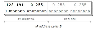 Class B IP address bits are always set to 10 so the first byte is always a value between 128-191. Network ID is the first 16 bits and 16 bits are the host ID so that if any computer has the IP address 167.205.26.161, the network ID and host ID = 167 205 = 26 161. On. Class B IP address has IP range from 128.0.xxx.xxx to 191.155.xxx.xxx, which amounted to 65 255 network by the number of hosts per network host 255 x 255 or about 65 thousand hosts.
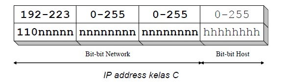
The structure of class C IP Address
 Class C IP address originally used for small networks such as LANs. The first three bits of a class C IP address is always set to 111. Network ID consists of 24 bits and 8 bits of remaining host ID so it can be formed about 2 million networks with each network has 256 hosts.
Class D and E are not used in general, a class D is used for multicast network, the first 4 bits of the class D IP address is always set 1110 so the first byte ranges between 224-247, while the next bit is set as necessary multicast group.
The structure of class D IP Address

Class E for experimental keprluan, class E IP address is not made available for public use. The first four bits of the IP address of this class is set 1111 so the first byte ranges between 248-255.
The structure of class E IP Address :

Network addresses used by routers to find a place a local computer network is located, while address local computer is used to identify a computer on the local network.
IP version 4 (IPv4 address is often called) is a type of network addressing that is used in network protocol TCP / IP using the IP protocol version 4. Total length is 32-bits, and can theoretically address on a host computer up to 4 billion or more precisely 4,294,967,296 hosts around the world, the number of hosts was obtained from 256 (obtained from 8 bits) dipangkat 4 (because there are 4 octets) so that the value maximum of alamt IP version 4 is 255.255.255.255 where the value is calculated from zero so that the value of the host that can be accommodated is 256x256x256x256 = 4,294,967,296 hosts. so that when a host of global quota then be made exceed the IP version 6 or IPv6.
Examples of version 4 IP address is 192.168.0.3
SUBNETTING
we have to master the concept of subnetting to get new IP address, which in this way we can create a new network ID of a network that we had before. Subnetting is use to break up a single network into several smaller networks. To reproduce the network ID of an existing network id, where the host ID sacrificed in part for use in making additional ID
Remember the formula to find a lot of subnets is 2 n - 2
N = number of bits that are shrouded in
And the formula to find number of hosts per subnet is 2 m - 2
M = number of bits that have not been shrouded in
Examples of cases with the completion of I:
Ip address 130.200.0.0 with a subnet mask of 255.255.224.0 identified as class B.
Subnet mask: 11111111.11111111.11100000.00000000
3 bits of the octet to 3 have been used, tingal 5 bits that have not been shrouded in so many groups of subnets that can be used is a multiple of 2 5 = 32 (256-224 = 32)
32 64 96 128 160 192 224
So the IP group that can be used dalah;
loopback subnet 130.200.0.0 - 130.200.31.254
130.200.32.1 - 130.200.63.254
130.200.64.1 - 130.200.95.254
130.200.96.1 - 130 200 127 254
130.200.128.1 - 130 200 159 254
130.200.160.1 - 130 200 191 254
130.200.192.1 - 130 200 223 254
Case:
An emerging company has many branches and each branch office has 255 workstations, network address is 164.10.0.0 available, create a subnet with the largest number of subnets
Settlement; 164.10.0.0 is in class B, meaning octet 3 and 4 are used for the host, whereas a branch office there are 254 hosts, then take a bit longer than the third octet so pretty.
So the new subnetmask
11111111.11111111.11111110.00000000
255. 255. 254. 0
Subnet that is available is 256-254 = 2, then the subnet multiples of 2 up to 254.
The number of subnets (2 7-2) = 128-2 = 26 subnets
The number of hosts / subnet (2 9-2) = 512-2 = 510 hosts
164.10.0.0 to 164.10.1.0 discarded
164.10.2 .1 to 164.10.3.254
164.10.4.1 to 164.10.5.254
164.10.6.1 to 164.10.7.254
164.10.8.1 to 164.10.9.254
164.10.252.1 to 164.10.253.254
Examples of practice subnetting: class B address
Network address 172.16.0.0 and the subnet mask of 255.255.192.0
Subnet 192 = 11 million, 2 2-2 = 2
Host 2 14 - 2 = 16 382 (6 bits in the third octet, and 8 bits in the fourth octet)
Valid subnet 256-192 = 64. 64 + 64 = 128
Subnet 64.0 128.0
The first host 64.1 128.1
Last Host 127 254 192 254
Broadcast 127 255 199 255
Description, then the 172.16.64.0 subnet or 64.0, 64.1 or have first host 172.16.64.1 to 171.16.127.254 and 172.16.127.255 broadcastnya address
Examples of practice subnetting: class A address
Network address 10.0.0.0 and subnet mask 255.255.0.0
Subnet 255 = 11111111, 2 8-2 = 254
Host 2 16 - 2 = 65 534
Valid subnet 256-255 = 1, 2, 3 and so on. (all in second octet). Subnet to be 10.1.0.0, 10.2.0.0, 10.3.0.0 and so on until 10.254.0.0
Subnet 10.1.0.0 10.254.0.0 ...
The first host 10.254.0.1 10.1.0.1 ...
Last Host 10.1.255.254 ... 10,254,255,254
Broadcast 10.1.255.255 ... 10,254,255,255
IP addresses can be separated into two parts, namely the network (net ID) and the host (host ID). Net ID instrumental in the identification of a network from another network, while the host ID serves to identify a host within a network. Thus, all hosts are connected in the same network have the same net ID. Some of the bits of the early part of the IP Address is the network bits / network number, while the rest is for the host. The dividing line between the network and hosts are not fixed, depending on the class network. IP addresses are divided into five classes, namely class A, class B, class C, class D and class E.
Determination of the class is done in the following ways:
The structure of class A IP Address :

The structure of class B IP Address :

The structure of class C IP Address
Class D and E are not used in general, a class D is used for multicast network, the first 4 bits of the class D IP address is always set 1110 so the first byte ranges between 224-247, while the next bit is set as necessary multicast group.
The structure of class D IP Address

Class E for experimental keprluan, class E IP address is not made available for public use. The first four bits of the IP address of this class is set 1111 so the first byte ranges between 248-255.
The structure of class E IP Address :

Network addresses used by routers to find a place a local computer network is located, while address local computer is used to identify a computer on the local network.
IP version 4 (IPv4 address is often called) is a type of network addressing that is used in network protocol TCP / IP using the IP protocol version 4. Total length is 32-bits, and can theoretically address on a host computer up to 4 billion or more precisely 4,294,967,296 hosts around the world, the number of hosts was obtained from 256 (obtained from 8 bits) dipangkat 4 (because there are 4 octets) so that the value maximum of alamt IP version 4 is 255.255.255.255 where the value is calculated from zero so that the value of the host that can be accommodated is 256x256x256x256 = 4,294,967,296 hosts. so that when a host of global quota then be made exceed the IP version 6 or IPv6.
Examples of version 4 IP address is 192.168.0.3
SUBNETTING
we have to master the concept of subnetting to get new IP address, which in this way we can create a new network ID of a network that we had before. Subnetting is use to break up a single network into several smaller networks. To reproduce the network ID of an existing network id, where the host ID sacrificed in part for use in making additional ID
Remember the formula to find a lot of subnets is 2 n - 2
N = number of bits that are shrouded in
And the formula to find number of hosts per subnet is 2 m - 2
M = number of bits that have not been shrouded in
Examples of cases with the completion of I:
Ip address 130.200.0.0 with a subnet mask of 255.255.224.0 identified as class B.
Subnet mask: 11111111.11111111.11100000.00000000
3 bits of the octet to 3 have been used, tingal 5 bits that have not been shrouded in so many groups of subnets that can be used is a multiple of 2 5 = 32 (256-224 = 32)
32 64 96 128 160 192 224
So the IP group that can be used dalah;
loopback subnet 130.200.0.0 - 130.200.31.254
130.200.32.1 - 130.200.63.254
130.200.64.1 - 130.200.95.254
130.200.96.1 - 130 200 127 254
130.200.128.1 - 130 200 159 254
130.200.160.1 - 130 200 191 254
130.200.192.1 - 130 200 223 254
Case:
An emerging company has many branches and each branch office has 255 workstations, network address is 164.10.0.0 available, create a subnet with the largest number of subnets
Settlement; 164.10.0.0 is in class B, meaning octet 3 and 4 are used for the host, whereas a branch office there are 254 hosts, then take a bit longer than the third octet so pretty.
So the new subnetmask
11111111.11111111.11111110.00000000
255. 255. 254. 0
Subnet that is available is 256-254 = 2, then the subnet multiples of 2 up to 254.
The number of subnets (2 7-2) = 128-2 = 26 subnets
The number of hosts / subnet (2 9-2) = 512-2 = 510 hosts
164.10.0.0 to 164.10.1.0 discarded
164.10.2 .1 to 164.10.3.254
164.10.4.1 to 164.10.5.254
164.10.6.1 to 164.10.7.254
164.10.8.1 to 164.10.9.254
164.10.252.1 to 164.10.253.254
Examples of practice subnetting: class B address
Network address 172.16.0.0 and the subnet mask of 255.255.192.0
Subnet 192 = 11 million, 2 2-2 = 2
Host 2 14 - 2 = 16 382 (6 bits in the third octet, and 8 bits in the fourth octet)
Valid subnet 256-192 = 64. 64 + 64 = 128
Subnet 64.0 128.0
The first host 64.1 128.1
Last Host 127 254 192 254
Broadcast 127 255 199 255
Description, then the 172.16.64.0 subnet or 64.0, 64.1 or have first host 172.16.64.1 to 171.16.127.254 and 172.16.127.255 broadcastnya address
Examples of practice subnetting: class A address
Network address 10.0.0.0 and subnet mask 255.255.0.0
Subnet 255 = 11111111, 2 8-2 = 254
Host 2 16 - 2 = 65 534
Valid subnet 256-255 = 1, 2, 3 and so on. (all in second octet). Subnet to be 10.1.0.0, 10.2.0.0, 10.3.0.0 and so on until 10.254.0.0
Subnet 10.1.0.0 10.254.0.0 ...
The first host 10.254.0.1 10.1.0.1 ...
Last Host 10.1.255.254 ... 10,254,255,254
Broadcast 10.1.255.255 ... 10,254,255,255
Selasa, 01 November 2011
802.xx Implementations
IEEE 802.1X is an IEEE Standard for port-based Network Access Control (PNAC). It is part of the IEEE 802.1 group of networking protocols. It provides an authentication mechanism to devices wishing to attach to a LAN or WLAN.
IEEE 802.1X defines the encapsulation of the Extensible Authentication Protocol (EAP) over IEEE 802[1][2] which is known as "EAP over LAN" or EAPOL.[3] EAPOL was originally designed for IEEE 802.3 Ethernet in 802.1X-2001, but was clarified to suit other IEEE 802 LAN technologies such as IEEE 802.11 wireless and Fiber Distributed Data Interface (ISO 9314-2) in 802.1X-2004.[4] The EAPOL protocol was also modified for use with IEEE 802.1AE (“MACsec”) and IEEE 802.1AR (Secure Device Identity, DevID) in 802.1X-2010.[5][6] to support service identification and optional point to point encryption over the local LAN segment.
Overview
802.1X authentication involves three parties: a supplicant, an authenticator, and an authentication server. The supplicant is a client device (such as a laptop) that wishes to attach to the LAN/WLAN - though the term 'supplicant' is also used interchangeably to refer to the software running on the client that provides credentials to the authenticator. The authenticator is a network device, such as an Ethernet switch or wireless access point; and the authentication server is typically a host running software supporting the RADIUS and EAP protocols.
The authenticator acts like a security guard to a protected network. The supplicant (i.e., client device) is not allowed access through the authenticator to the protected side of the network until the supplicant’s identity has been validated and authorized. An analogy to this is providing a valid passport at an airport before being allowed to pass through security to the terminal. With 802.1X port-based authentication, the supplicant provides credentials, such as user name / password or digital certificate, to the authenticator, and the authenticator forwards the credentials to the authentication server for verification. If the authentication server determines the credentials are valid, the supplicant (client device) is allowed to access resources located on the protected side of the network.[7]
Protocol operation

Port entities 802.1X-2001 defines two logical port entities for an authenticated port the "controlled port" and the "uncontrolled port". The controlled port is manipulated by the 802.1X PAE (Port Access Entity) to allow (in the authorized state) or prevent (in the unauthorized state) network traffic ingressing and egressing to/from the controlled port. The uncontrolled port is used by the 802.1X PAE to transmit and receive EAPOL frames.
802.1X-2004 defines the equivalent port entities for the supplicant; so a supplicant implementing 802.1X-2004 may prevent higher level protocols being used if it is not content that authentication has successfully completed. This is particularly useful when an EAP method providing Mutual Authentication is used, as the supplicant can prevent data leakage when connected to an unauthorized network.
[edit]Typical authentication progression
1. Initialization On detection of a new supplicant, the port on the switch (authenticator) is enabled and set to the "unauthorized" state. In this state, only 802.1X traffic is allowed; other traffic, such as DHCP and HTTP, is dropped.
2. Initiation To initiate authentication the authenticator will periodically transmit EAP-Request Identity frames to a special Layer 2 address on the local network segment. The supplicant listens on this address, and on receipt of the EAP-Request Identity frame it responds with an EAP-Response Identity frame containing an identifier for the supplicant such as a User ID. The authenticator then encapsulates this Identity response in a RADIUS Access-Request packet and forwards it on to the authentication server. The supplicant may also initiate or restart authentication by sending an EAPOL-Start frame to the authenticator, which will then reply with an EAP-Request Identity frame.
3. Negotiation (Technically EAP negotiation) The authentication server sends a reply (encapsulated in a RADIUS Access-Challenge packet) to the authenticator, containing an EAP Request specifying the EAP Method (The type of EAP based authentication it wishes the supplicant to perform). The authenticator encapsulates the EAP Request in an EAPOL frame and transmits it to the supplicant. At this point the supplicant can NAK the requested EAP Method and respond with the EAP Methods it is willing to perform, or start the requested EAP Method.
4. Authentication If the authentication server and supplicant agree on an EAP Method, EAP Requests and Responses are sent between the supplicant and the authentication server (translated by the authenticator) until the authentication server responds with either an EAP-Success message (encapsulated in a RADIUS Access-Accept packet), or an EAP-Failure message (encapsulated in a RADIUS Access-Reject packet). If authentication is successful, the authenticator sets the port to the "authorized" state and normal traffic is allowed, if it is unsuccessful the port remains in the "unauthorized" state. When the supplicant logs off, it sends an EAPOL-logoff message to the authenticator, the authenticator then sets the port to the "unauthorized" state, once again blocking all non-EAP traffic.
Media Transmisi
On any network, the various entities must communicate through some form of media. Just as humans can communicate through telephone wires or sound waves in the air, computers can communicate through cables, light, and radio waves. Transmission media enable computers to send and receive messages but do not guarantee that the messages will be understood.
Some of the most common network transmission media, such as coaxial cable, shielded twisted-pair cable, and unshielded twisted-pair cable, network fiber-optic cable and wireless communications.
1. Twisted-Pair Cable

Twisted-pair cable has become the dominant cable type for all new network designs that employ copper cable. Among the several reasons for the popularity of twisted-pair cable, the most significant is its low cost. Twisted-pair cable is inexpensive to install and offers the lowest cost per foot of any cable type.
A basic twisted-pair cable consists of two strands of copper wire twisted together This twisting reduces the sensitivity of the cable to EMI and also reduces the tendency of the cable to radiate radio frequency noise that interferes with nearby cables and electronic components. This is because the radiated signals from the twisted wires tend to cancel each other out. (Antennas, which are purposely designed to radiate radio frequency signals, consist of parallel, not twisted, wires.)
Twisting also controls the tendency of the wires in the pair to cause EMI in each other. Whenever two wires are in close proximity, the signals in each wire tend to produce noise, called crosstalk, in the other. Twisting the wires in the pair reduces crosstalk in much the same way that twisting reduces the tendency of the wires to radiate EMI.
2. Coaxial cables

Coaxial cables were the first cable types used in LANs. Coaxial cable gets its name because two conductors share a common axis; the cable is most frequently referred to as a coax.
The components of a coaxial cable are as follows:
* A center conductor, although usually solid copper wire, sometimes is made of stranded wire.
* An outer conductor forms a tube surrounding the center conductor. This conductor can consist of braided wires, metallic foil, or both. The outer conductor, frequently called the shield, serves as a ground and also protects the inner conductor from EMI.
* An insulation layer keeps the outer conductor spaced evenly from the inner conductor.
* A plastic encasement (jacket) protects the cable from damage.
3. Fiber optics cable
 optical fiber
In almost every way, fiber-optic cable is the ideal cable for data transmission. Not only does this type of cable accommodate extremely high bandwidths, but it also presents no problems with EMI and supports durable cables and cable runs as long as several kilometers. The two disadvantages of fiber-optic, however, are cost and installation difficulty.
The center conductor of a fiber-optic cable is a fiber that consists of highly refined glass or plastic designed to transmit light signals with little loss. A glass core supports a longer cabling distance, but a plastic core is typically easier to work with. The fiber is coated with a cladding that reflects signals back into the fiber to reduce signal loss.
Fiber-optic network cable consists of two strands separately enclosed in plastic sheaths—one strand sends and the other receives. Two types of cable configurations are available: loose and tight configurations. Loose configurations incorporate a space between the fiber sheath and the outer plastic encasement; this space is filled with a gel or other material. Tight configurations contain strength wires between the conductor and the outer plastic encasement. In both cases, the plastic encasement must supply the strength of the cable, while the gel layer or strength wires protect the delicate fiber from mechanical damage.
Optical fiber cables don’t transmit electrical signals. Instead, the data signals must be converted into light signals. Light sources include lasers and light-emitting diodes (LEDs). LEDs are inexpensive but produce a fairly poor quality of light suitable for less-stringent applications.
A laser is a light source that produces an especially pure light that is monochromatic (one color) and coherent (all waves are parallel). The most commonly used source of laser light in LAN devices is called an injection laser diode (ILD). The purity of laser light makes lasers ideally suited to data transmissions because they can work with long distances and high bandwidths. Lasers, however, are expensive light sources used only when their special characteristics are required.
The end of the cable that receives the light signal must convert the signal back to an electrical form. Several types of solid-state components can perform this service.
One of the significant difficulties of installing fiber-optic cable arises when two cables must be joined. The small cores of the two cables (some are as small as 8.3 microns) must be lined up with extreme precision to prevent excessive signal loss.
4.Wireless
Wireless Media The extraordinary convenience of wireless communications has placed an increased emphasis on wireless networks in recent years. Technology is expanding rapidly and will continue to expand into the near future, offering more and better options for wireless networks.

The following sections describe these technologies and some of the networking options available with each.
Wireless point-to-point communications are another facet of wireless LAN technology.

Point-to-point wireless technology specifically facilitates communications between a pair of devices (rather than attempting to achieve an integrated networking capability). For instance, a point-to-point connection might transfer data between a laptop and a home-based computer or between a computer and a printer. Point-to-point signals can pass through walls, ceilings, and other obstructions. Point-to-point provides data transfer rates of 1.2 to 38.4 Kbps for a range of up to 200 feet indoors (or one third of a mile for line-of-sight broadcasts).
Some of the most common network transmission media, such as coaxial cable, shielded twisted-pair cable, and unshielded twisted-pair cable, network fiber-optic cable and wireless communications.
1. Twisted-Pair Cable

Twisted-pair cable has become the dominant cable type for all new network designs that employ copper cable. Among the several reasons for the popularity of twisted-pair cable, the most significant is its low cost. Twisted-pair cable is inexpensive to install and offers the lowest cost per foot of any cable type.
A basic twisted-pair cable consists of two strands of copper wire twisted together This twisting reduces the sensitivity of the cable to EMI and also reduces the tendency of the cable to radiate radio frequency noise that interferes with nearby cables and electronic components. This is because the radiated signals from the twisted wires tend to cancel each other out. (Antennas, which are purposely designed to radiate radio frequency signals, consist of parallel, not twisted, wires.)
Twisting also controls the tendency of the wires in the pair to cause EMI in each other. Whenever two wires are in close proximity, the signals in each wire tend to produce noise, called crosstalk, in the other. Twisting the wires in the pair reduces crosstalk in much the same way that twisting reduces the tendency of the wires to radiate EMI.
2. Coaxial cables

Coaxial cables were the first cable types used in LANs. Coaxial cable gets its name because two conductors share a common axis; the cable is most frequently referred to as a coax.
The components of a coaxial cable are as follows:
* A center conductor, although usually solid copper wire, sometimes is made of stranded wire.
* An outer conductor forms a tube surrounding the center conductor. This conductor can consist of braided wires, metallic foil, or both. The outer conductor, frequently called the shield, serves as a ground and also protects the inner conductor from EMI.
* An insulation layer keeps the outer conductor spaced evenly from the inner conductor.
* A plastic encasement (jacket) protects the cable from damage.
3. Fiber optics cable

In almost every way, fiber-optic cable is the ideal cable for data transmission. Not only does this type of cable accommodate extremely high bandwidths, but it also presents no problems with EMI and supports durable cables and cable runs as long as several kilometers. The two disadvantages of fiber-optic, however, are cost and installation difficulty.
The center conductor of a fiber-optic cable is a fiber that consists of highly refined glass or plastic designed to transmit light signals with little loss. A glass core supports a longer cabling distance, but a plastic core is typically easier to work with. The fiber is coated with a cladding that reflects signals back into the fiber to reduce signal loss.
Fiber-optic network cable consists of two strands separately enclosed in plastic sheaths—one strand sends and the other receives. Two types of cable configurations are available: loose and tight configurations. Loose configurations incorporate a space between the fiber sheath and the outer plastic encasement; this space is filled with a gel or other material. Tight configurations contain strength wires between the conductor and the outer plastic encasement. In both cases, the plastic encasement must supply the strength of the cable, while the gel layer or strength wires protect the delicate fiber from mechanical damage.
Optical fiber cables don’t transmit electrical signals. Instead, the data signals must be converted into light signals. Light sources include lasers and light-emitting diodes (LEDs). LEDs are inexpensive but produce a fairly poor quality of light suitable for less-stringent applications.
A laser is a light source that produces an especially pure light that is monochromatic (one color) and coherent (all waves are parallel). The most commonly used source of laser light in LAN devices is called an injection laser diode (ILD). The purity of laser light makes lasers ideally suited to data transmissions because they can work with long distances and high bandwidths. Lasers, however, are expensive light sources used only when their special characteristics are required.
The end of the cable that receives the light signal must convert the signal back to an electrical form. Several types of solid-state components can perform this service.
One of the significant difficulties of installing fiber-optic cable arises when two cables must be joined. The small cores of the two cables (some are as small as 8.3 microns) must be lined up with extreme precision to prevent excessive signal loss.
4.Wireless
Wireless Media The extraordinary convenience of wireless communications has placed an increased emphasis on wireless networks in recent years. Technology is expanding rapidly and will continue to expand into the near future, offering more and better options for wireless networks.

The following sections describe these technologies and some of the networking options available with each.
Wireless point-to-point communications are another facet of wireless LAN technology.

Point-to-point wireless technology specifically facilitates communications between a pair of devices (rather than attempting to achieve an integrated networking capability). For instance, a point-to-point connection might transfer data between a laptop and a home-based computer or between a computer and a printer. Point-to-point signals can pass through walls, ceilings, and other obstructions. Point-to-point provides data transfer rates of 1.2 to 38.4 Kbps for a range of up to 200 feet indoors (or one third of a mile for line-of-sight broadcasts).
Senin, 31 Oktober 2011
Network Applications
Network Applications
 Network applications may be defined as software applications used in networks that require or substantially benefit from the presence of networked computers. Networks essentially are
created in order to connect users and facilitate the performance of tasks. Networks therefore exist for applications. Without applications software, users can do little on a network. Network application software allows users to tap the power of networks in increasingly creative ways.
Currently network applications can be classified into three kinds :
network-ignorant
network-aware
network-intrinsic
Network-ignorant applications are essentially standalone applications that can be hosted on a single file server and be made available to all users on a network. Users can run the application on their desktops and make changes on files available through the application. However, there is no concurrency control, if two users try to use the application simultaneously, data can be lost or corrupted.
Network-aware applications are very similar to network-ignorant applications in that they too offer single copy hosting on a server, and access by multiple users over a network. However, the difference is concurrency control.
Network-aware applications such as Paradox offer the advantages of record- or file-locking, which locks down a record or file in use by any user on a network, thus preventing overwrites by other users. Most client-server applications today are network-aware applications. Their primary value lies in using the network to extend the abilities of a PC and to share network resources.
Network-intrinsic applications include distributed databases, compile servers, compute servers, and multitasking communications servers. Network operating systems today are seeking to provide more multitasking, more memory, faster processors, and programming interfaces in order to make network-intrinsic programs more powerful.
 Some of the more common uses of network applications include using a web browser program to find content from the World Wide Web, or using an e-mail program to send e-mails over the Internet.
Network applications are selected based on the type of work that needs to be done. A complete set of application-layer programs is available to interface with the Internet. Each application program type is associated with its own application protocol. Some examples include:
1. HTTP is the World-Wide-Web communications protocol used to connect to web servers. Its primary function is to establish a connection with a web server and transmit HTML pages to the client browser.
2. Post Office Protocol 3 (POP3) is an application-layer protocol supported by e-mail programs for the retrieval of electronic mail. POP3 is a standard e-mail server commonly used on the Internet.
3. File Transfer Protocol (FTP) is a simple file utility program for transferring files between remote computers, which also provides for basic user authentication.
4. Telnet is a remote access application and protocol for connecting to remote computer consoles, which also provides for basic user authentication.
5. Simple Network Management Protocol (SNMP) is used by network management programs for monitoring the network device status and activities.
The 7 Layers of the OSI Model
The Open Systems Interconnection model (OSI model) is a product of the Open Systems Interconnection effort at the International Organization for Standardization. It is a prescription of characterizing and standardizing the functions of a communications system in terms of abstraction layers.
The OSI model consists of seven layers:
Application
Presentation
Session
Transport
Network
Data Link
Physical
What do the seven layer OSI?
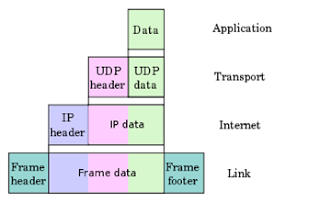
 When data is transferred over the network, before the data must pass through all seven layers of a single terminal, ranging from physical layer to application layer, then on the receiving side, the data ispassed through physical layer applications. At the time of datathrough one layer of the sending side, it will add a "header" while onthe receiving end "header" in accordance with layernya removed.

 TCP/IP Model
The TCP/IP model is a description framework for computer network protocols created in the 1970s by DARPA, an agency of the United States Department of Defense. It evolved from ARPANET, which was the world's first wide area network and a predecessor of the Internet. The TCP/IP Model is sometimes called the Internet Model or the DoD Model.

created in order to connect users and facilitate the performance of tasks. Networks therefore exist for applications. Without applications software, users can do little on a network. Network application software allows users to tap the power of networks in increasingly creative ways.
Currently network applications can be classified into three kinds :
network-ignorant
network-aware
network-intrinsic
Network-ignorant applications are essentially standalone applications that can be hosted on a single file server and be made available to all users on a network. Users can run the application on their desktops and make changes on files available through the application. However, there is no concurrency control, if two users try to use the application simultaneously, data can be lost or corrupted.
Network-aware applications are very similar to network-ignorant applications in that they too offer single copy hosting on a server, and access by multiple users over a network. However, the difference is concurrency control.
Network-aware applications such as Paradox offer the advantages of record- or file-locking, which locks down a record or file in use by any user on a network, thus preventing overwrites by other users. Most client-server applications today are network-aware applications. Their primary value lies in using the network to extend the abilities of a PC and to share network resources.
Network-intrinsic applications include distributed databases, compile servers, compute servers, and multitasking communications servers. Network operating systems today are seeking to provide more multitasking, more memory, faster processors, and programming interfaces in order to make network-intrinsic programs more powerful.

Network applications are selected based on the type of work that needs to be done. A complete set of application-layer programs is available to interface with the Internet. Each application program type is associated with its own application protocol. Some examples include:
1. HTTP is the World-Wide-Web communications protocol used to connect to web servers. Its primary function is to establish a connection with a web server and transmit HTML pages to the client browser.
2. Post Office Protocol 3 (POP3) is an application-layer protocol supported by e-mail programs for the retrieval of electronic mail. POP3 is a standard e-mail server commonly used on the Internet.
3. File Transfer Protocol (FTP) is a simple file utility program for transferring files between remote computers, which also provides for basic user authentication.
4. Telnet is a remote access application and protocol for connecting to remote computer consoles, which also provides for basic user authentication.
5. Simple Network Management Protocol (SNMP) is used by network management programs for monitoring the network device status and activities.
The 7 Layers of the OSI Model
The Open Systems Interconnection model (OSI model) is a product of the Open Systems Interconnection effort at the International Organization for Standardization. It is a prescription of characterizing and standardizing the functions of a communications system in terms of abstraction layers.
The OSI model consists of seven layers:
Application
Presentation
Session
Transport
Network
Data Link
Physical
What do the seven layer OSI?


The TCP/IP model is a description framework for computer network protocols created in the 1970s by DARPA, an agency of the United States Department of Defense. It evolved from ARPANET, which was the world's first wide area network and a predecessor of the Internet. The TCP/IP Model is sometimes called the Internet Model or the DoD Model.
Senin, 26 September 2011
Network Topologies
NETWORK TOPOLOGY
A network topologi defines how computer and Other device are connected. A network topology describes the layout of the wire
And device as well as the path used by data transmissions.
Kind of physical topology that are commonly used are now:
- Bus
- ring
- hierarchical
- Star
- extended star
- mesh
Bus topology
Bus topology connects all the devices using a single cable.
This cable proceeds from the computer to the next like a bus line
going thourgh a city.
 figure.bus topology
with bus topology,the main cable segment must end with a
terminator that absorb thi signal when it reaches the end of the line
or ware. Bus topologies were common in the early days of LANs
That used single coaxial cable.
Ring topology
The ring topology is another important topology in Lan
connectivity. Unlike the physical bus topology,the ring topology
has no beginning or the end that needs to be terminated.
a frame travels around the ring,stoping at each node. If a node
wants to transmit data,it is permitted to add that data as well
as the destination address to the frame.
Then continues around the
Ring until it finds the destinations node, which takes data out of
the frame.
 Figure.ring topology
Two type of ring topology :
Single ring = in a single ring,all the device on the network
Shere a single cable,and the data travels in one direction only.
Dual ring = two ring allow data to be sent in both directions,
If both ring fail, a WRAP at the fault can heal the topology back
Into a ring.
Star and Extended Star Topology
The star topology, is the most commonly used physical topology in
Ethernet LANs. the star topology is made up of a central
connections poin that is a device such as a HUB,SWITCH,or
ROUTER, where all the cabling segment meet. the network is
Connected to the central device with its own cable.
while Extended Star Topology is when a star network is expanded
to include an additional networking device that is connected to the
main networking device.
 Figure.Star Topology
 Figure.Extended-star
( Star topologies and Expanded-star
become more apparent in later chapters when switch and routers
are discussed in more detail).
Hierarchical Topology
a hierarchical topology is created similary to an extended star
topology. The primary difference is that it does not use a central
mode.
 Figure.Hierarchical Topology
Mesh Topology
Two types of the mesh topology :
Full mesh topologies, connects all device to each other for
redundacy and fault tolerance. The wiring in a Full Mesh topology
has very distinct advantages and disadvantages.
Implementing a full mesh topology is expensive and difficult. And
the mash topology is ussualy inplemented in WANs between
router.

Figure.full Mesh topologies
In partial mesh topology,at least one device maintains multiple connections to other with out being full mested. The partial mesh topology is used for many telecommunications backbone,as well internet
A network topologi defines how computer and Other device are connected. A network topology describes the layout of the wire
And device as well as the path used by data transmissions.
Kind of physical topology that are commonly used are now:
- Bus
- ring
- hierarchical
- Star
- extended star
- mesh
Bus topology
Bus topology connects all the devices using a single cable.
This cable proceeds from the computer to the next like a bus line
going thourgh a city.

with bus topology,the main cable segment must end with a
terminator that absorb thi signal when it reaches the end of the line
or ware. Bus topologies were common in the early days of LANs
That used single coaxial cable.
Ring topology
The ring topology is another important topology in Lan
connectivity. Unlike the physical bus topology,the ring topology
has no beginning or the end that needs to be terminated.
a frame travels around the ring,stoping at each node. If a node
wants to transmit data,it is permitted to add that data as well
as the destination address to the frame.
Then continues around the
Ring until it finds the destinations node, which takes data out of
the frame.

Two type of ring topology :
Single ring = in a single ring,all the device on the network
Shere a single cable,and the data travels in one direction only.
Dual ring = two ring allow data to be sent in both directions,
If both ring fail, a WRAP at the fault can heal the topology back
Into a ring.
Star and Extended Star Topology
The star topology, is the most commonly used physical topology in
Ethernet LANs. the star topology is made up of a central
connections poin that is a device such as a HUB,SWITCH,or
ROUTER, where all the cabling segment meet. the network is
Connected to the central device with its own cable.
while Extended Star Topology is when a star network is expanded
to include an additional networking device that is connected to the
main networking device.


( Star topologies and Expanded-star
become more apparent in later chapters when switch and routers
are discussed in more detail).
Hierarchical Topology
a hierarchical topology is created similary to an extended star
topology. The primary difference is that it does not use a central
mode.

Mesh Topology
Two types of the mesh topology :
Full mesh topologies, connects all device to each other for
redundacy and fault tolerance. The wiring in a Full Mesh topology
has very distinct advantages and disadvantages.
Implementing a full mesh topology is expensive and difficult. And
the mash topology is ussualy inplemented in WANs between
router.

Figure.full Mesh topologies
In partial mesh topology,at least one device maintains multiple connections to other with out being full mested. The partial mesh topology is used for many telecommunications backbone,as well internet
Langganan:
Komentar (Atom)